
Calculating a fiber link loss budget requires summing the maximum attenuation of fiber segments, connector pairs, and splices. For OS2 at 1310nm and OM4 at 850nm, this calculation ensures optical power stays within the receiver's sensitivity range, preventing bit errors and network downtime in high-speed telecommunications infrastructure.
Identify maximum fiber attenuation based on TIA-568.3-E standards for OS2 and OM4 media.
Calculate total link loss by summing fiber length, connector counts, and fusion splice quantities.
Incorporate a 2.0 dB to 3.0 dB safety margin to account for component aging and repairs.
Validate theoretical budgets against field measurements using OTDR or optical power meter testing methods.
An optical link loss budget represents the total signal reduction allowed for a specific fiber optic link to operate correctly. This budget ensures the received power level stays within the operational range of the active network equipment's optical receivers. Engineers must define these limits before installation to prevent costly rework or hardware incompatibility issues in high-speed environments.
According to the Telecommunications Industry Association (TIA), loss is primarily caused by absorption, scattering, and macro-bending within the cable. In a typical point-to-point connection, the budget includes the attenuation of the fiber itself plus losses from every connection point. According to TIA-568.3-E, the standard provides a framework for these calculations across different fiber categories.
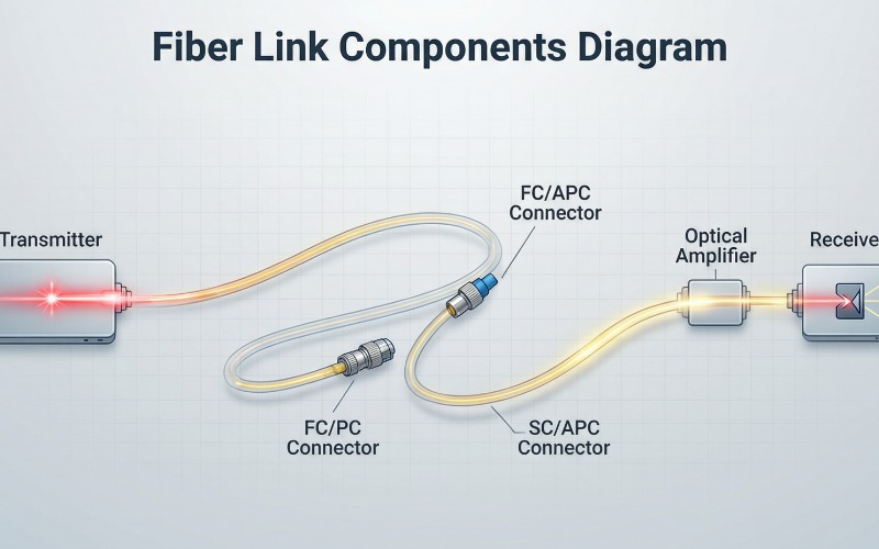
Precision in loss calculation directly impacts the reliability of 40G, 100G, and 400G Ethernet deployments in modern data centers. As data rates increase, the allowable power loss, or "loss envelope," becomes significantly tighter for the network hardware. For instance, the IEEE 802.3bm standard specifies a maximum channel loss of only 1.9 dB for 100GBASE-SR4 over OM4.
Exceeding this budget leads to high Bit Error Rates (BER), which degrade network throughput and increase latency for users. Field research by the Fiber Optic Association (FOA) indicates that 95% of performance issues stem from poor link budgeting. Proper calculation allows procurement managers to select high-quality OS2 (Optical Singlemode 2) or OM4 (Optical Multimode 4) components early.
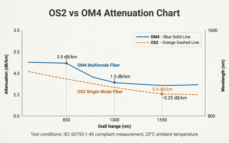
OS2 fiber is designed for long-distance transmission using wavelengths of 1310nm or 1550nm with a typical core diameter of 9 microns. The attenuation rate for OS2 is remarkably low, typically cited as 0.4 dB/km at 1310nm and 0.3 dB/km at 1550nm. According to ITU-T G.652.D, these values are the maximum permissible for standard low-water-peak singlemode fibers used globally.
When calculating the OS2 budget, start by multiplying the total distance in kilometers by the attenuation coefficient of the fiber. For a 10km link at 1310nm, the fiber loss would be 10 multiplied by 0.4, resulting in 4.0 dB. This baseline must then be augmented by the losses contributed by connectors and fusion splices throughout the route.
OM4 is a laser-optimized multimode fiber with a 50-micron core, primarily utilized for short-reach applications in high-density data center environments. It operates at 850nm and 1300nm wavelengths, with the 850nm window being the most common for VCSEL (Vertical-Cavity Surface-Emitting Laser) transceivers. The ISO/IEC 11801 standard defines the maximum attenuation for OM4 at 3.5 dB/km at the 850nm wavelength.
Because OM4 links are usually shorter, connector loss often represents the largest portion of the total link budget compared to fiber attenuation. In a 150-meter data center link, the fiber attenuation is only 0.525 dB, while four connector pairs could add 3.0 dB. Engineers must prioritize low-loss LC or MPO connectors to stay within the 1.9 dB limit required for 100G speeds.
The standard formula for determining the total link loss (L) is expressed as L = (a × d) + (n × c) + (s × f) + m. In this equation, 'a' represents fiber attenuation per kilometer, and 'd' represents the total distance of the cable run. The variable 'n' counts the connector pairs, while 'c' stands for the maximum loss per mated connector pair.
Furthermore, 's' denotes the number of splices, and 'f' represents the loss per splice, typically 0.1 dB for fusion splicing. Finally, 'm' is the safety margin, which accounts for component aging, environmental factors, and future repairs that might occur. Most enterprise designs utilize a safety margin between 2.0 dB and 3.0 dB to ensure long-term operational stability and performance.
| Component Type | TIA-568.3-E Max Loss | Unitekfiber Ultra-Low Loss | Primary Test Wavelength |
|---|---|---|---|
| OS2 Fiber Attenuation | 0.5 dB/km | 0.35 dB/km | 1310 nm |
| OM4 Fiber Attenuation | 3.5 dB/km | 3.0 dB/km | 850 nm |
| LC Connector Pair | 0.75 dB | 0.15 dB | All Wavelengths |
| MPO/MTP Connector | 0.75 dB | 0.35 dB | 850 nm / 1310 nm |
| Fusion Splice Loss | 0.30 dB | 0.05 dB | All Wavelengths |
According to data from NIST (National Institute of Standards and Technology), utilizing ultra-low loss components can increase reach by 40%. This performance gap is critical for architects designing spine-leaf architectures where multiple cross-connects are required between the server and switch. Lowering connector loss from 0.75 dB to 0.15 dB allows for more flexible patching without violating the power budget.
The choice between standard connectors and ultra-low loss (ULL) connectors is the most significant variable in modern fiber link design. Standard connectors following TIA-568 limits allow for 0.75 dB of loss, which is often too high for high-density environments. At Unitekfiber, we have observed that ULL connectors provide the necessary headroom for 400GBASE-DR4 applications which have extremely tight budgets.
Using MPO-12 or MPO-24 connectors also introduces different loss profiles compared to traditional duplex LC connectors due to alignment complexities. According to a 2024 study by BICSI, 68% of technicians struggle with link budgets when using high-density MPO breakout cassettes. Selecting factory-terminated, pre-tested fiber patch cords reduces the uncertainty associated with field-terminated connectors and ensures consistent loss values across the link.
The design budget is a theoretical calculation based on the worst-case specifications of the components selected for the fiber link. In contrast, the measured loss is the actual attenuation recorded by an Optical Time Domain Reflectometer (OTDR) after installation. It is common for measured loss to be lower than the design budget because manufacturers typically over-specify maximum loss values.
However, if the measured loss exceeds the design budget, it indicates a failure in installation quality or contaminated connector end-faces. Research from IEEE suggests that contamination is responsible for nearly 80% of link failures in data center environments. Technicians must clean and inspect every connector according to the IEC 61300-3-35 standard before performing final certification tests.
A safety margin, also known as a system gain margin, is vital for protecting the network against unforeseen future changes. This margin typically ranges from 2.0 dB for short-haul enterprise links to 3.0 dB for critical long-haul telecommunications infrastructure. It accounts for the inevitable degradation of laser sources over time and the potential for future emergency fusion splices.
According to the Corning Engineering Standards, a safety margin also compensates for temperature fluctuations that can affect fiber attenuation. In outdoor environments, extreme cold can cause micro-bends in the cable jacket, slightly increasing the link's total optical loss. Including a robust margin ensures that the network remains functional even as the physical plant ages over its twenty-year lifespan.
For a 100GBASE-SR4 link over OM4 fiber, the maximum allowable channel loss is 1.9 dB according to IEEE 802.3bm standards. This includes all connectors and cable attenuation over a maximum distance of 100 meters, requiring high-precision components.
OS2 fiber has a lower attenuation rate (0.4 dB/km) and is designed for outdoor or long-haul use compared to OS1. OS1 is typically used indoors with a higher attenuation of 1.0 dB/km, making OS2 budgets much more efficient for distances.
Higher than expected loss is usually caused by dirty connectors, excessive cable bending, or poor-quality splices during the installation process. Always clean connectors with isopropyl alcohol or specialized cleaning tools before re-testing the link with an optical power meter.
Yes, patch cords at both ends of the link contribute to the total loss and must be included in the calculation. Each connection point where a patch cord meets the bulk cabling adds a connector pair loss to the overall budget.
 5G 6G Fronthaul & Backhaul
View More
5G 6G Fronthaul & Backhaul
View More
 Data Center & Cloud Interconnect
View More
Data Center & Cloud Interconnect
View More
 Enterprise & Industrial Optical
View More
Enterprise & Industrial Optical
View More
 FTTx & Access Solutions
View More
FTTx & Access Solutions
View More
 Metro & Access Networks
View More
Metro & Access Networks
View More
 Optical Cabling Systems
View More
Optical Cabling Systems
View More
 Optical Transceivers & Interconnect
View More
Optical Transceivers & Interconnect
View More
 WDM & High-Capacity Transmission
View More
WDM & High-Capacity Transmission
View More
+86-755-21034367