Fiber optical PLC splitters and fiber optic couplers are passive optical devices that are used to split an optical signal into at least 2 and as many as 256 signals. They are widely used in FTTx architectures to provide service for up to 256 users from a single optical signal. UnitekFiber as a professional fiber optic PLC splitters manufacturer provides customized a serial of PLC splitters, such as 1x2 fiber optic couplers, steel tube PLC splitters, ABS Cassette fiber optical PLC splitter, LGX Box fiber optical PLC splitter or etc.
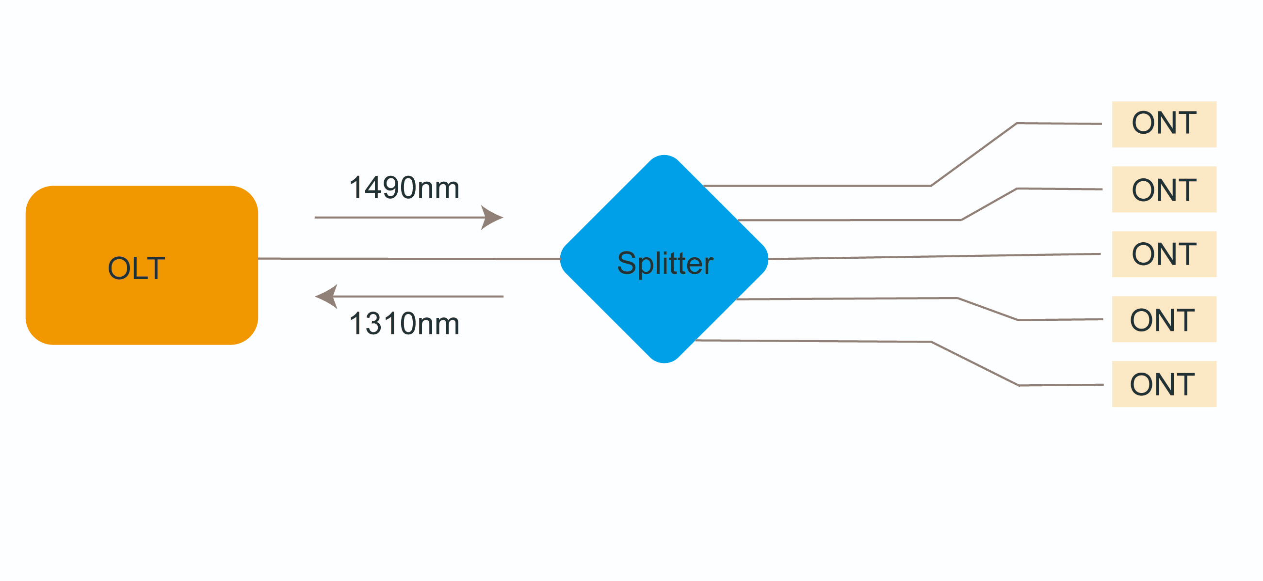
PLC splitter, also called Planar Waveguide Circuit Splitter, is a device used to divide one or two light beams into multiple light beams uniformly or combine multiple light beams to one or two light beams. It is a passive optical device with many input and output terminals, especially applicable to PON (EPON, GPON, BPON, FTTX, etc.) to connect the MDF (main distribution frame) and the terminal equipment and to branch the optical signal.
Fiber Optic PLC splitter is used for splitting a single optical signal into multiple signals. It takes a single input and divides it into several outputs, allowing one optical fiber to serve multiple users or devices. Fiber PLC splitters work based on the principle of light splitting using a planar lightwave circuit. They use a combination of waveguides and optical splitters fabricated on a small chip to divide the incoming optical signal into multiple outputs. Fiber PLC splitter is passive devices that do not require additional transmitters or receivers. They are usually installed at the central office or distribution point and split the incoming optical signal into multiple outputs to serve multiple users or devices.
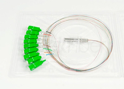
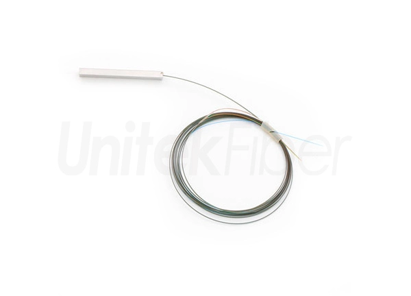
The bare ribbon fiber optical PLC splitter has no connector at the ends of bare optical fiber. One key feature of the bare fiber plc splitter is its compact and space-saving design. This type of PLC splitter is commonly used in various network architectures, including passive optical networks (PONs) and fiber-to-the-home (FTTH) systems etc.
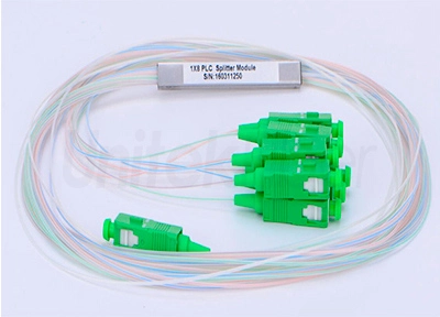
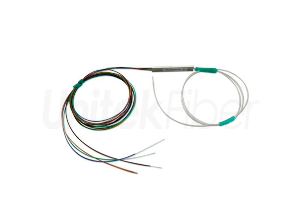
The steel tube fiber optical PLC splitter consists of an optical fiber array and a steel tube, whereas the blockless PLC splitter has a similar appearance to the bare ribbon fiber optical PLC splitter. However, the compact stainless steel tube packaging provides better protection for optical fibers. This design offers increased durability and reliability, making steel tube fiber optical PLC splitter an ideal choice for applications where fiber protection is crucial.
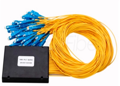
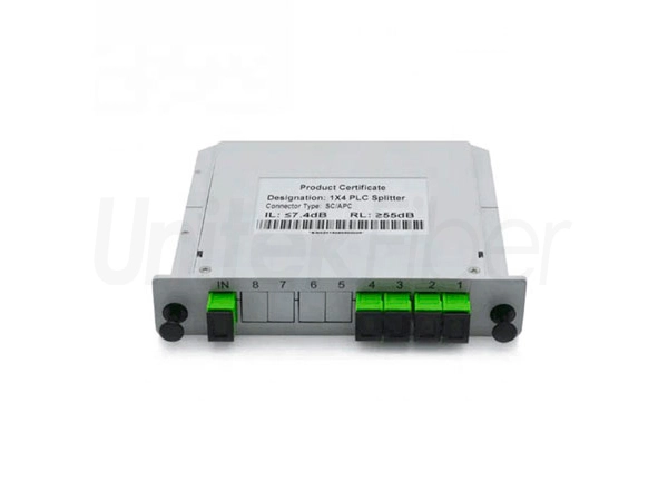
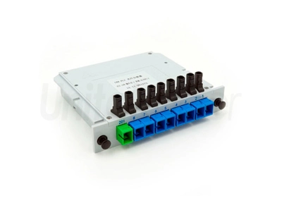
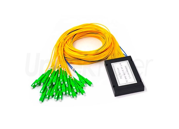
The ABS module PLC splitter has a plasetic ABS cassette, it is commonly used housing for fiber optic splitters due to its durability, lightweight, and cost-effectiveness. It provides protection for the delicate internal components and keeps the fibers properly organized. The ABS material also offers good resistance to impact, moisture, and temperature variations, making ABS cassette PLC splitter suitable for various indoor and outdoor installation environments.
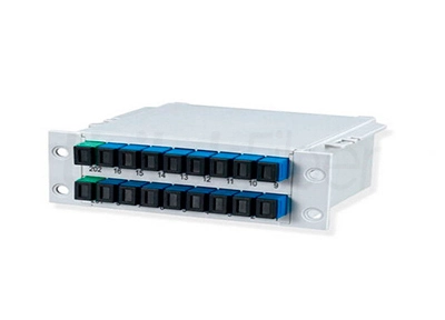
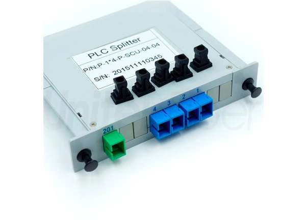
The LGX Box PLC splitter typically consists of a metal or plastic enclosure with a removable front panel. It can be used alone or easily installed in a standard fiber optic patch panel or fiber optic chassis. The LGX box PLC splitter provides a convenient and modular solution for housing fiber PLC splitter as it allows for easy installation, removal, and maintenance of the fiber PLC splitter module.
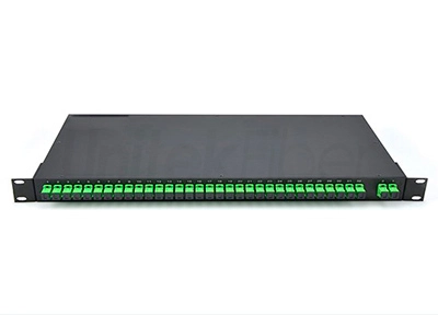
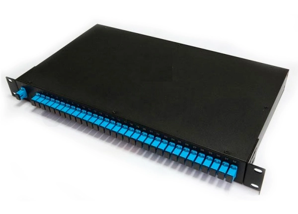
The rack mount fiber PLC splitter is designed to be mounted in a standard 19 inch equipment rack or cabinet. It can be manufactured in various configurations, such as 1U, 2U, or 4U sizes. Rack mount fiber PLC splitter typically used in data centers, server rooms, and telecommunications facilities.
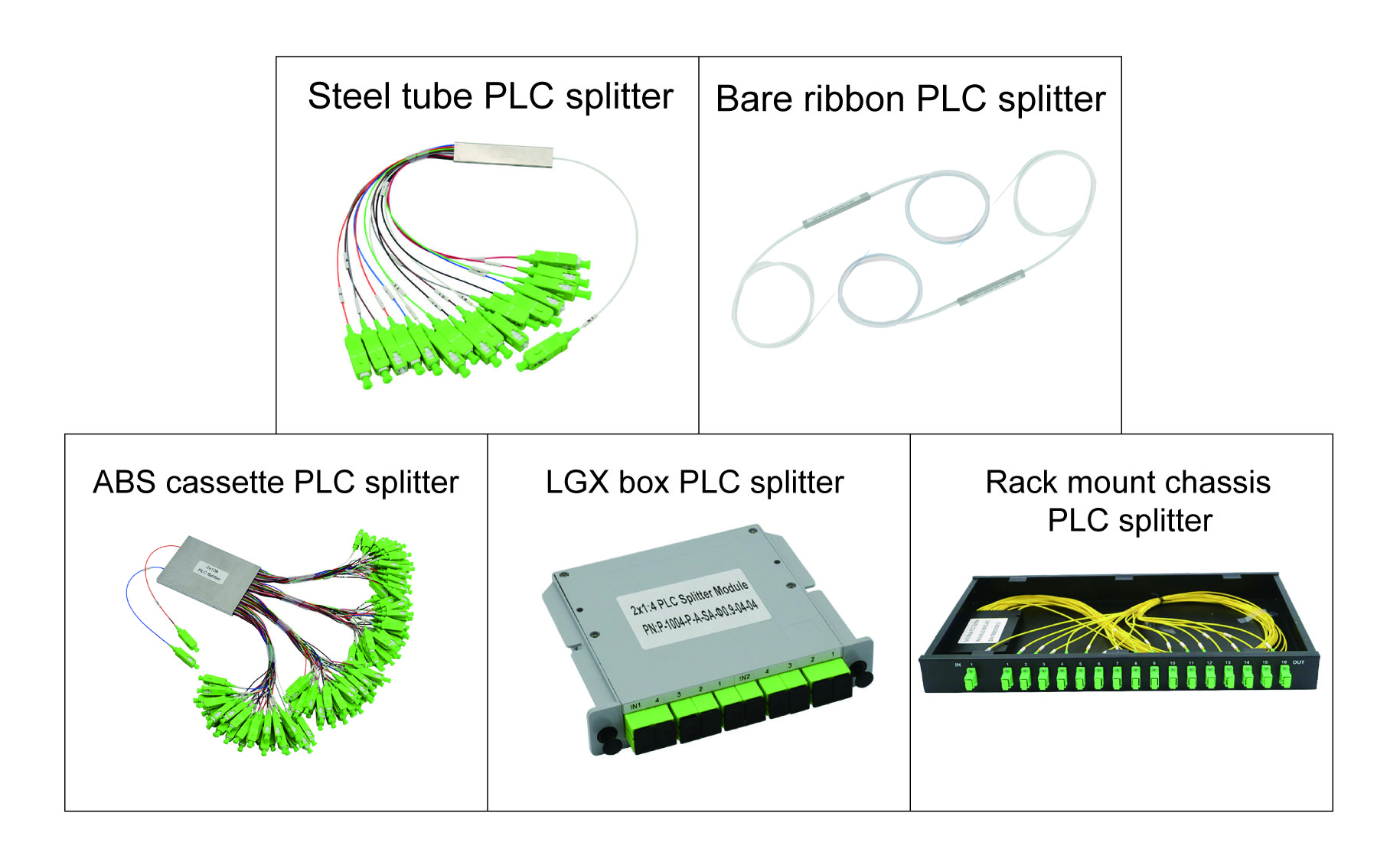
UnitekFiber as a professional manufacturer of fiber optic PLC spliiter, can provide comprehensive types of fiber optic PLC splitter, such as bare ribbon PLC splitter, steel tube PLC splitter, ABS cassette PLC splitter, LGX box PLC splitter and rack mount PL splitter etc. We are so glad to support you and to establish a business cooperation with you. Please contact us at Email sales@unitekfiber.com if you have any inquiry.
PLC splitter, also called Planar Waveguide Circuit Splitter, is a device used to divide one or two light beams into multiple light beams uniformly or combine multiple light beams to one or two light beams. It is a passive optical device with many input and output terminals, especially applicable to PON (EPON, GPON, BPON, FTTX, etc.) to connect the MDF (main distribution frame) and the terminal equipment and to branch the optical signal.
Fiber Optic PLC splitter is used for splitting a single optical signal into multiple signals. It takes a single input and divides it into several outputs, allowing one optical fiber to serve multiple users or devices. Fiber PLC splitters work based on the principle of light splitting using a planar lightwave circuit. They use a combination of waveguides and optical splitters fabricated on a small chip to divide the incoming optical signal into multiple outputs. Fiber PLC splitter is passive devices that do not require additional transmitters or receivers. They are usually installed at the central office or distribution point and split the incoming optical signal into multiple outputs to serve multiple users or devices.

The bare ribbon fiber optical PLC splitter has no connector at the ends of bare optical fiber. One key feature of the bare fiber plc splitter is its compact and space-saving design. This type of PLC splitter is commonly used in various network architectures, including passive optical networks (PONs) and fiber-to-the-home (FTTH) systems etc.
The steel tube fiber optical PLC splitter consists of an optical fiber array and a steel tube, whereas the blockless PLC splitter has a similar appearance to the bare ribbon fiber optical PLC splitter. However, the compact stainless steel tube packaging provides better protection for optical fibers. This design offers increased durability and reliability, making steel tube fiber optical PLC splitter an ideal choice for applications where fiber protection is crucial.
The ABS module PLC splitter has a plasetic ABS cassette, it is commonly used housing for fiber optic splitters due to its durability, lightweight, and cost-effectiveness. It provides protection for the delicate internal components and keeps the fibers properly organized. The ABS material also offers good resistance to impact, moisture, and temperature variations, making ABS cassette PLC splitter suitable for various indoor and outdoor installation environments.
The LGX Box PLC splitter typically consists of a metal or plastic enclosure with a removable front panel. It can be used alone or easily installed in a standard fiber optic patch panel or fiber optic chassis. The LGX box PLC splitter provides a convenient and modular solution for housing fiber PLC splitter as it allows for easy installation, removal, and maintenance of the fiber PLC splitter module.
The rack mount fiber PLC splitter is designed to be mounted in a standard 19 inch equipment rack or cabinet. It can be manufactured in various configurations, such as 1U, 2U, or 4U sizes. Rack mount fiber PLC splitter typically used in data centers, server rooms, and telecommunications facilities.

UnitekFiber as a professional manufacturer of fiber optic PLC spliiter, can provide comprehensive types of fiber optic PLC splitter, such as bare ribbon PLC splitter, steel tube PLC splitter, ABS cassette PLC splitter, LGX box PLC splitter and rack mount PL splitter etc. We are so glad to support you and to establish a business cooperation with you. Please contact us at Email sales@unitekfiber.com if you have any inquiry.


